Analyzing the Flashlight Circuit
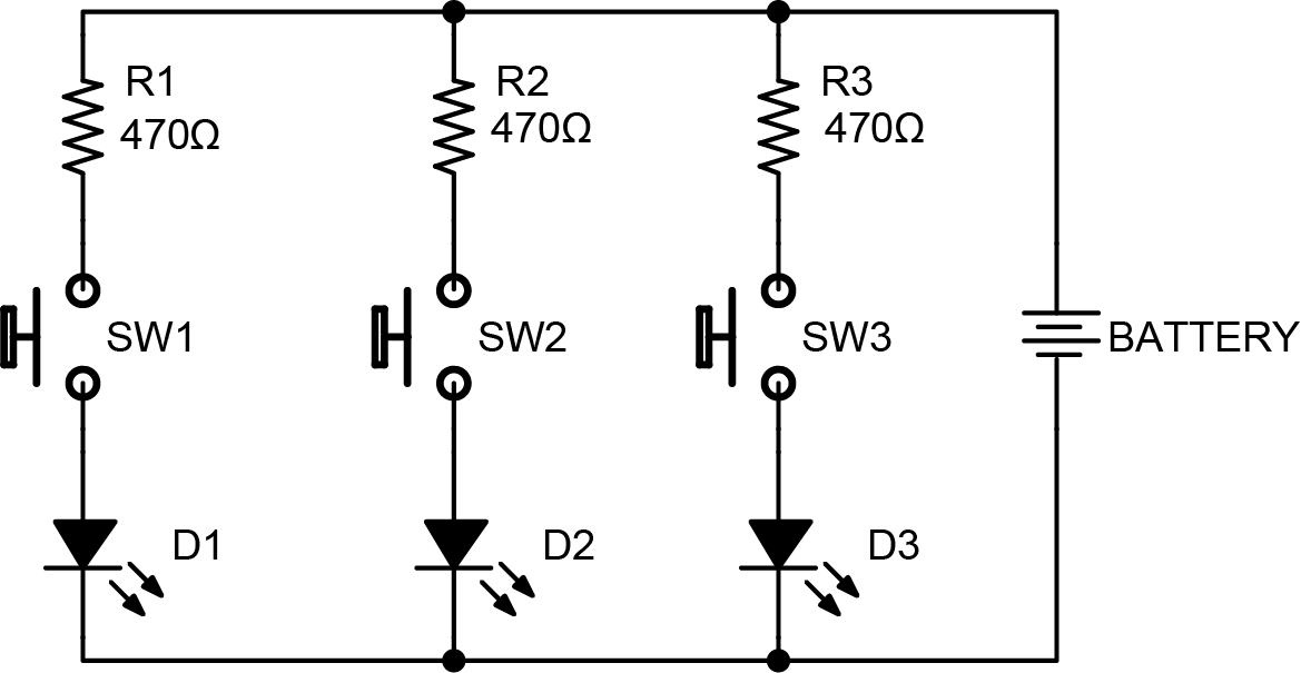
Since the buttons are "normally open," i.e., not connecting one side to the other, there's no path for the charge on one side of the battery to return to the other. Current does not flow through the circuit.
When you press a button you close the circuit, creating a path between the positive and negative sides of the battery. Refer to the schematic here and see how the SW1, SW2, and SW3 buttons open and close the path from one side of the battery to the other.
D1, D2, and D3 are the LEDs, which light up when current flows through them.
LEDs are light emitting diodes, and like other diodes only allow current to flow one direction through them. We need the cathode (the short leg, if you recall) to be on the more negative side of the circuit, or the negative terminal of the battery in this case.
Each LED has a resistor in series (in the same path) with it to limit how much current can flow through that branch of the circuit. Without it the LED would draw too much current and burn itself out. The resistor can be on either side of the LED, as long as it limits the only only path the current can take to go through the LED.
Resistor Values: For Future Reference
Choosing a resistor value for an LED is usually best done by trial and error. Different colors will have varying brightness. Values between 220Ω and 10kΩ (10,000Ω) are the most common. The higher the value, the more it resists the flow of current, and therefore the dimmer your LED will be. The lower the resistor value, the brighter your LED will be.There are calculators online that purport to tell you which resistor to use for a given LED, but these usually just calculate the lowest possible value that will prevent the LED from immediately burning out. Using their recommended resistor will not only waste power, but will probably make your LED uncomfortably bright.

