Reading Schematics
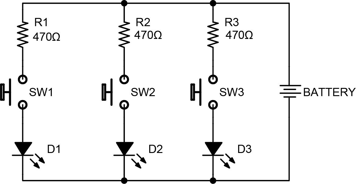
A schematic is the primary way we communicate electrical circuits. It's a drawing of the electrical paths and connections between the components that make up the circuit. Here is the schematic for our flashlight project:
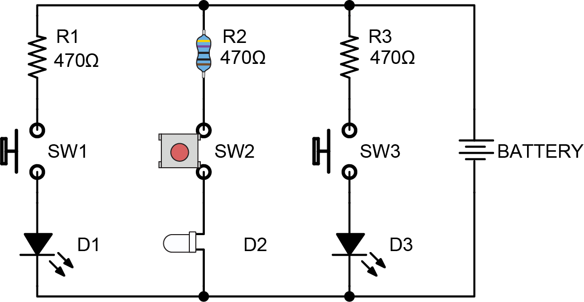
Now let's replace the R2, SW2, and D2 symbols with illustrations of those components to show how the schematic is very nearly a drawing of the actual physical circuit.
Symbols and Designators
Different symbols are used to represent different types of components. Here are some that appear in this schematic:
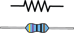
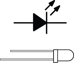
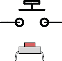

You can find a list of the most common symbols here.
Reference designators are a combination of letters and numbers that uniquely identify a component in the circuit. e.g., R1 is resistor 1, SW2 is switch 2, and D3 and diode 3.
Along with the reference designator a schematic will also list the numeric value of a component, if it has one. For example our resistors all have a value of 470Ω. The Greek letter omega (Ω) stands for Ohms, the unit of electrical resistance. You can learn more about this in our How Pedals Work book (coming soon)
Nets: Electrical Connections
Nets are what we call the connections between components. They are most commonly drawn with lines that represent electrical paths, typically either wires or copper traces on the PCB.
The dots where lines intersect indicate those paths are connected. If some of the intersections don't have dots, those paths are NOT connected electrically.
An alternate convention, which isn't used in this book and is shown here for future reference, is to omit the dots and assume an electrical connection when lines intersect UNLESS the line curves when crossing paths with another.
Net Symbols
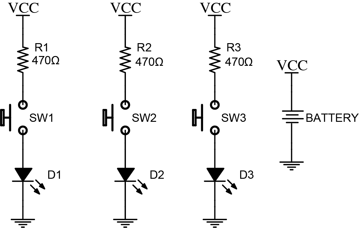
Nets are often drawn with lines, as seen above, but we can also use special net symbols. We use these to keep the schematic drawing tidy and to avoid having too many criss-crossing or distracting lines.
Any lines connected to a net symbol are assumed to be connected to any others connected to the same symbol.
Ground (or GND) and the positive voltage (often VCC), or reference voltage (often VBIAS or VREF) are the most common, but you may see others too.
The following two schematics are equivalent. They use conventional net symbols for GND and voltage sources.
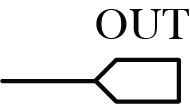
You may also see other nets labeled with flags such as this:
Ground Net
Ground Nets
One of the most common points of confusion I see in DIY pedal forums is when people are talking about what to "ground to." They want to ground their pedal "to" something.
While you probably could form a correct answer around such questions, it'll serve you better to simply throw out the notion and instead think of the GND as any other net. Ground points in your circuit are simply points that are connected TO EACH OTHER. That's it.
GND is special in that it's a shared reference point (remember a voltage is a difference in charge between two measured points, of which GND is commonly used as one) between your guitar pedal, amplifier, and guitar. The sleeve of the instrument cable is used as a common connection between all these circuits. It lets them measure voltage differences from a commmon reference point.

