Ribbon Cable
PICKUP SIMULATOR
Building the pickup simulator?
If you're planning to build the pickup simulator sub-kit, pause here to do that now. See the instructional sheet that came with your kit, or click here to learn more. Watch the build video here.
Individual wires are most commonly used to connect the PCB to the jacks and foot switch, but somtimes you’ll find other connectors such as this ribbon cable. Although more expensive, ribbon cables are a convenient way to keep the wiring tidy, prevent mistakes, and make the buid process quicker and easier.
The insulation is pre-cut at both ends of the included ribbon cables. Pull it off one end. Leave the other end covered to prevent accidentally bending the wires while you work.
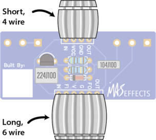
Insert the wires into the side of the PCB with the rectangle printed on it, as shown in this illustration. If your cable has a red stripe on one side, disregard it. We're not using the stripe to signify anything so the ribbon can be inserted in either direction.
The ribbons will stick up on the same side as the rest of the components you have attached so far.
Turn the board over and solder each of the wires. Gravity should hold it in place, but if it doesn't want to sit flat, use a little blue putty from your practice kit to keep things where you want them.
WHAT DOES IT DO?
Ribbon Cables
The top ribbon cable carries the IN and OUT signals to/from the phone jacks, as well as the GND and VCC (9V) DC voltage levels to/from the power supply.
The bottom ribbon cable goes to the foot switch and caries those same 4 voltages, but also the input to this main PCB (FI) and the output to this PCB (FO).
Eliminating the #1 Source of DIY Pedal Problems
Compared to traditional "off-board wiring" to the jacks and foot switch, these ribbon cables greatly simplify the build and remove a common source of errors. Traditionally you would run individual wires as shown here, and painstakingly connect over a dozen points.

