
Current Limiting Resistor (CLR) for LED
Start the Foot Switch PCB
Find the foot switch PCB, which has a 3x3 grid of pads for the lugs on the foot switch.
We are going to start but NOT finish this PCB, so don't jump ahead! Namely, we aren't yet ready to attach the foot switch or the LED, and we'll instead attach those after they're mounted in the enclosure. (Really you could do them now, but the foot switch would be bulky to deal with in the intermediate steps, and the LED's height and spacing would be hard to get right).
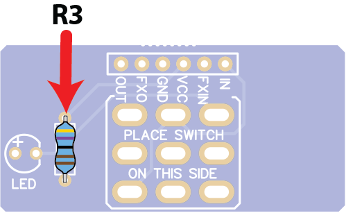
Solder Current Limiting Resistor (CLR) for LED
Solder R3 just as you did the resistors on the main PCB.
WHAT DOES IT DO?
LED: lights up when the foot switch routes current through it
R3: limits the amount of current available to the LED, to prevent it from burning out. You will often see this called a CLR (Current Limiting Resistor). Some pedal bills of material won't provide a value for it since you can size it to your taste.
Customization tip: For a dimmer LED, try a larger value for R3 (not included) such as 10k or even 20k. To make it brighter, you can use a small value, e.g., between 220Ω and 1kΩ. We are using a common, moderate value of 4.7kΩ.