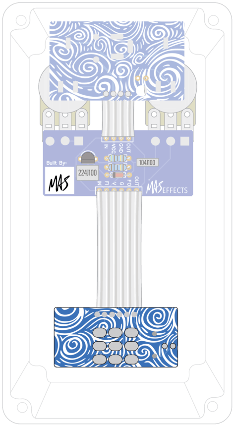
Install Foot Switch PCB
Foot Switch Installation
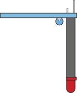
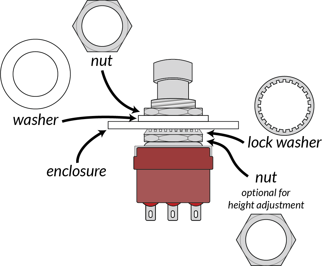
Look at the image below to see how the foot switch is installed in the enclosure.
If you like a short foot switch, first install a nut to limit its height. If you'd prefer a tall foot switch, you can omit this.
Next, put the lock washer (the washer with teeth) on the foot switch.
Install the foot switch into the enclosure. Secure the foot switch with the smooth washer, then the nut.
Tighten it with the provided wrench .
WHAT DOES IT DO?
Foot Switch
When the pedal is bypassed the foot switch connects the input jack tip (carries the input signal from the guitar) to the output jack tip (carries the signal to the amp). In other words, the signal passes directly from the input to output jack, bypassing the circuit. The switch also connects the PCB input to GND to help ensure any leaky DC voltage doesn't build up and cause a pop when we engage the pedal.
When the pedal is engaged, the input jack tip goes to the PCB input and the PCB output goes to the output jack tip. i.e., Your phone jacks are connected to the circuit. A DC voltage is also applied across the LED to power it and make it light up.
Customization Option
An easy way to further decorate your pedal is with alternate hardware for your foot switch. For example you can use...
- decorative aluminum nut instead of the nut and washer
- dress nut to fit over the nut and washer
- slim metal washer to replace the white plastic one
Take Note: LED Polarity
Orientation matters for LEDs (Light Emitting Diodes). Just like other diodes, they have a polarity. Current only flows through LEDs in one direction.
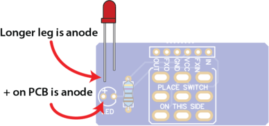
The longer lead, called an anode, goes on the positive side, which is marked with a "+" on the PCB.
The shorter lead, called a cathode, goes on the negative side, which is indicated on the PCB with a flat section of the LED outline. If you look closely at the LED itself, you'll find it also has a flat side, which is useful for determining the polarity if its leads have been clipped.
The shorter lead, called a cathode, goes on the negative side which is indicated on the PCB with a flat section of the LED outline, matching the flat side of the LED body.
LED Spacer
In your kit, you'll find a black spacer tube, with two channels cut into it to hold the leads of the LED. We will use this hold the LED at the approximate height we want. It's not necessary, but it helps make installation easier.
Slide the LED's leads into the spacer.
Insert the LED into the foot switch PCB being sure to get the polarity correct.
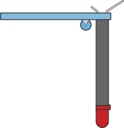
Bend its leads to hold the LED in place.
Do not solder it yet.
Solder Foot Switch
Place the foot switch PCB onto the foot switch, making sure it's resting firmly with the lugs sticking through the holes. If the PCB tends to move when you let go, use some blue putty (from your Soldering Practice Kit) to keep it in place.
Solder one lug, let it cool for about 5 seconds, then the PCB will be held firmly in place while you solder the rest of them.
If you're new to this, then allow 10 seconds to pass between each lug. Foot switch lugs require more heat than other joints you've done so far. That means you need to ensure a VERY good wet layer of solder on the iron's tip to transfer heat, and give it at least 2 seconds to heat up. You may need to run the tip back and forth on the foot switch lug to get solder to flow across the entire pad.
Like most components, unfortunately, too much heat can damage it. The epoxy in the foot switch can melt, resulting in mechanical failures.
Watch the video to see what this process should look like.
TIME CHECK
Apply heat for no more than 3-5 seconds! If you can't get the solder joint done in that time:
- Stop; remove heat
- Allow the joint to cool for about 10-20 seconds
- Tin your tip and ensure it's wet with solder, then touch it back to the joint. Make sure it's against both the foot switch lug and the pad
- Apply more solder as needed
- Stop after a few seconds. Repeat as needed.
Solder LED
Now that the foot switch and PCB are secured in position, we can set the final position of the LED. Make sure the LED is seated in the hole on the face of the enclosure, then solder its two leads. Clip the excess.

